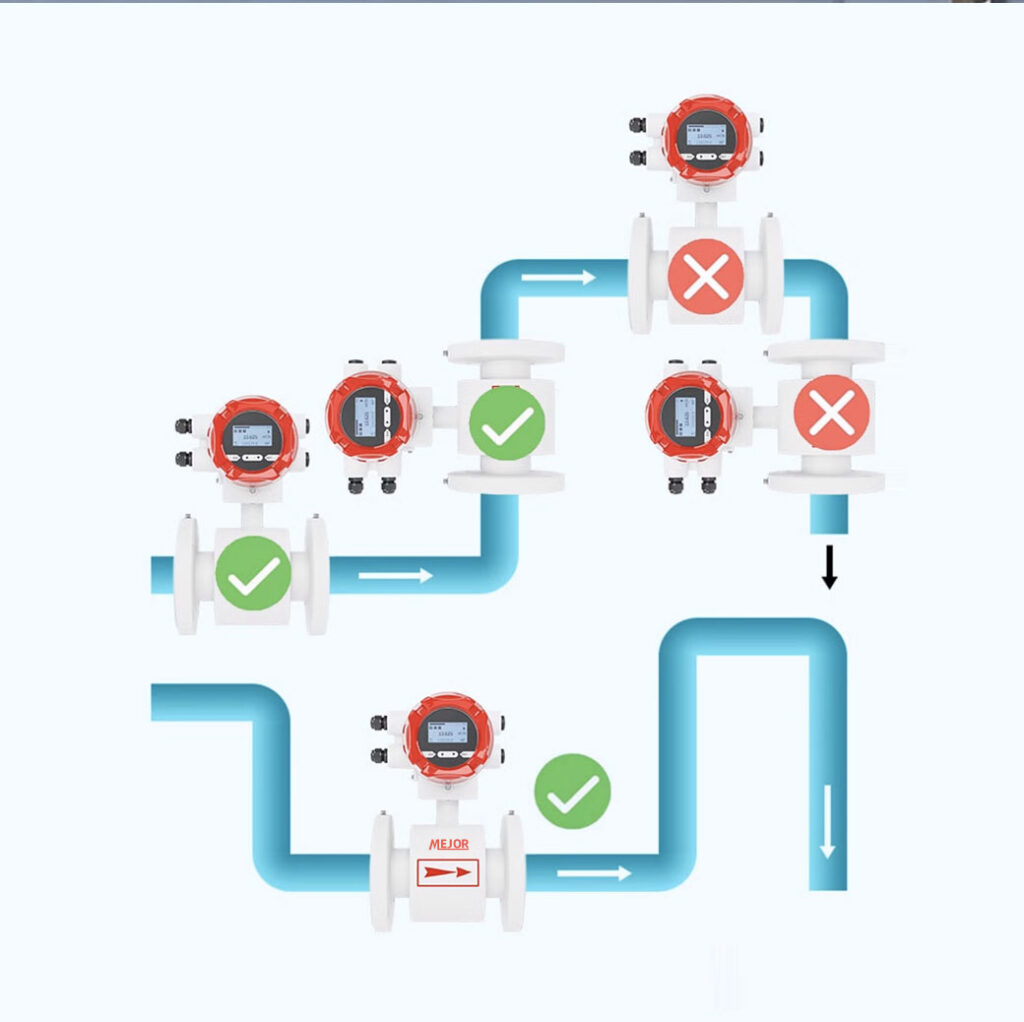
Electromagnetic flowmeter, as a high-precision flow measurement instrument, is widely used in various fields of industrial production. Correct installation is the key to ensuring its measurement accuracy, stability, and long-term reliable operation. This article will provide a detailed introduction to the installation points and process of electromagnetic flow meters.

Preparation work before installation:
Flow testing: Under actual operating conditions, use standard flow devices or other known flow devices to conduct flow testing on electromagnetic flow meters. Compare the measured value of the flowmeter with the standard value and calculate the measurement error. If the error exceeds the allowable range, the flowmeter needs to be parameter adjusted or recalibrated.
The installation of electromagnetic flow meters is a meticulous and critical task, and every step cannot be ignored. Only by strictly following the installation requirements and steps can the electromagnetic flowmeter ensure its optimal performance and provide accurate and reliable flow measurement data for industrial production.
Confirm pipeline parameters: Before installing the electromagnetic flowmeter, it is necessary to clarify the material, inner diameter, working pressure, temperature and other parameters of the pipeline. These data are crucial for selecting appropriate specifications of flow meters and determining installation methods. For example, if the inner diameter of the pipeline does not match the diameter of the flow meter, it will seriously affect the measurement accuracy.
Check the appearance of the flowmeter: Upon receiving the electromagnetic flowmeter, carefully inspect its appearance for any damage, such as cracked casing, scratched display screen, etc. At the same time, check if the randomly attached accessories are complete, including sensors, converters, installation flanges, gaskets, connecting cables, etc.
Cleaning the pipeline: Ensure that the interior of the pipeline within a certain length range upstream and downstream of the installation location is clean, free of debris, dirt, rust, etc. These impurities may interfere with the measurement and even damage the electrodes of the flowmeter. Chemical cleaning or mechanical cleaning can be used. After cleaning, the pipeline should be rinsed with clean water and drained completely.
Selection of installation location
Requirements for straight pipe sections: Electromagnetic flowmeters have strict requirements for upstream and downstream straight pipe sections. Generally speaking, the length of the upstream straight pipe section should not be less than 5 times the diameter of the pipeline, and the length of the downstream straight pipe section should not be less than 2 times the diameter of the pipeline. This is to ensure that the fluid maintains a stable velocity distribution when entering the flowmeter, reducing the impact of turbulence caused by pipeline bends, valves, etc. on measurement accuracy. For example, if there is an elbow upstream, the flow meter should be installed as far away from the elbow as possible.
Avoid interference sources: Keep away from strong electromagnetic interference sources such as large motors, transformers, frequency converters, etc. The electromagnetic fields generated by these devices may affect the signal transmission of electromagnetic flow meters, leading to measurement errors. At the same time, it is also necessary to avoid installation in environments with high temperature, high humidity, and corrosive gases to prevent damage to the electronic components of the flowmeter.
Fluid direction and installation method: Clarify the flow direction of the fluid and ensure that the arrow direction of the flowmeter is consistent with the fluid flow direction. According to the layout of the pipeline, electromagnetic flow meters can be installed horizontally, vertically, or diagonally. When installed vertically, the fluid should flow from bottom to top to ensure that the pipeline is always filled with liquid and avoid the accumulation of bubbles in the measuring tube that may affect the measurement.
Installation steps
Sensor installation: Firstly, align the installation flange of the sensor with the matching flange on the pipeline, and pay attention to the correct placement of the sealing gasket to ensure good sealing and prevent leakage. Then, use bolts to evenly tighten the flange, paying attention to the moderate tightening torque to avoid flange deformation or poor sealing caused by uneven force.
Converter installation: The converter should be installed in a dry, well ventilated, easy to operate and maintain place. It is usually installed in the dashboard or control cabinet on site. Connect the sensor to the converter using a connecting cable, and ensure that the shielding layer of the cable is reliably grounded to prevent external interference signals from entering.
Grounding treatment: Grounding of electromagnetic flow meters is very important, and good grounding is a necessary condition to ensure measurement accuracy and safe operation of equipment. The grounding electrode of the sensor should be reliably connected to the grounding grid through a dedicated grounding wire, and the grounding resistance should be less than the specified value (generally not greater than 100 Ω). If the pipeline is made of non-metallic material or lined with insulation material, a grounding ring needs to be installed on the pipeline to ensure a good electrical path between the fluid and the ground.
Debugging and inspection after installation
Power on inspection: After installation, turn on the power and check if the display screen of the electromagnetic flowmeter is displaying normally and if all indicator lights are working properly. Observe if there are any error messages in the flowmeter. If there are any abnormalities, troubleshoot according to the instructions.
Zero point calibration: Perform zero point calibration on the electromagnetic flowmeter when the pipeline is filled with stationary liquid and there is no flow. This step can eliminate measurement errors caused by sensor zero drift and other factors, ensuring that the flowmeter outputs zero at zero flow rate.
